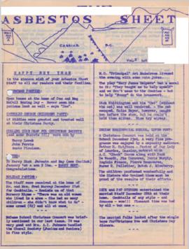
"The Asbestos Sheet" is a newspaper that documents the community and work life of the residents of Cassiar BC. Content includes text and photographs, as well as jokes, comics, and games.
On March 7, 1956 the Cassiar Reporters Guild published one issue of an untitled newspaper simply titled "The Cassiar '?'" (vol.1, no.1) along with a "name that newspaper" contest call out to the local community. It is believed that no other issue of this first volume was published until December 7, 1957 when The Asbestos Sheet (vol.2, no.1) was published. The Asbestos Sheet, was generally published twice a month and ran from December 1957 to September 1976; after which time both its name and its format changed: the 8-1/2 x 10" news bulletin changing to an 11 x 17" newspaper; and The Asbestos Sheet becoming the Cassiar Courier. The Courier was published monthly from fall 1976 until February 1991 when it stopped circulation shortly before the closure of both the mine and the company town.
On March 7, 1956 the Cassiar Reporters Guild published one issue of an untitled newspaper simply titled "The Cassiar?" (vol.1, no.1) along with a "name that newspaper" contest call out to the local community. It is believed that no other issue of this first volume was published until December 7, 1957 when The Asbestos Sheet (vol.2, no.1) was published. The Asbestos Sheet, was generally published twice a month and ran from December 1957 to September 1976; after which time both its name and its format changed: the 8-1/2 x 10" news bulletin changing to an 11 x 17" newspaper; and The Asbestos Sheet becoming the Cassiar Courier. The Courier was published monthly from fall 1976 until February 1991 when it stopped circulation shortly before the closure of both the mine and the company town.
The Publications series consists of news bulletins and newspapers documenting the community and work life of the residents of Cassiar, BC. Content includes text and photographs, as well as jokes, comics and games.
On March 7, 1956 the Cassiar Reporters Guild published one issue of an untitled newspaper simply titled “The Cassiar?” (vol.1, no.1) along with a “name that newspaper” contest call out to the local community. It is believed that no other issue of this first volume was published until December 7, 1957 when The Asbestos Sheet (vol.2, no.1) was published. The Asbestos Sheet, was generally published twice a month and ran from December 1957 to September 1976; after which time both its name and its format changed: the 8-1/2 x 10” news bulletin changing to an 11 x 17” newspaper; and The Asbestos Sheet becoming the Cassiar Courier. The Courier was published monthly from fall 1976 until February 1991 when it stopped circulation shortly before the closure of both the mine and the company town.
This map depicts the pit layout and estimated waste extraction areas for 6350 bench. Extraction dates accompanied by its total tonnages are located within each planned area. Annotated details include extraction dates, approximate total tonnages per area as well as extraction dates, total planned and broken tonnages and total tonnages from December 31, 1970 from a survey done in September 30. The hand drawn plan consists of solid lines drawn with red, green and orange colored pencils.
This map depicts the pit layout and estimated waste extraction areas for 5870 bench for the end of August to November. Extraction dates, approximate extraction tonnages and ore, waste and talus locations are included throughout the plan. Annotated details include numerical bench markers, extraction dates, approximate extraction tonnages, ore, waste and talus locations as well as waste, ore, talus and total tonnage calculations for October. The hand drawn plan consists of solid and broken lines drawn with red, blue, orange and lead pencils as well as black ink.
This map depicts the pit layout and estimated waste extraction areas for 5840 bench for the end of September to November. Extraction dates, approximate extraction tonnages and ore, waste and talus locations are included throughout the plan. Annotated details include numerical bench markers, extraction dates, approximate total tonnages as well as waste and ore tonnage calculations for October. The hand drawn plan consists of solid and broken lines drawn with red, blue, orange and lead pencils as well as black ink.
This map depicts the pit layout and estimated waste extraction areas for 6320 bench for the end of September to October. Extraction dates are included within certain portions of the plan. Annotated details include numerical bench markers, extraction dates, and approximate waste tonnage calculation for October. The hand drawn plan consists of solid and broken lines drawn with red, orange and lead pencils as well as black ink.
This map depicts the generalized pit layout and estimated waste extraction areas for 6290 bench for the month of October and November. Extraction dates as well as total unbroken tonnages are included within certain portions of the plan. Annotated details include numerical bench markers, extraction dates, total tonnages to be extracted and approximate waste tonnage calculations for October. The hand drawn plan consists of solid and broken lines drawn with red, green, orange and lead pencils as well as black ink.
This map depicts the generalized pit layout and estimated waste extraction areas for 6290 bench for the month of November. Annotated details include numerical bench markers and waste extraction dates. The hand drawn plan consists of solid and dotted lines drawn with green, orange, red, blue and lead pencil.
This map depicts the generalized pit layout and estimated waste extraction areas for 5810 bench. Annotated details include numerical bench markers, extraction dates and approximate ore extraction amounts. The hand drawn plan consists of solid and dotted lines drawn with green, orange and lead pencil.
This map depicts the generalized pit layout and estimated waste extraction areas for benches 5840 and 5870. Annotated details include numerical bench markers as well as extraction dates. The hand drawn plan consists of solid and dotted lines drawn with green and red pencil.
This map depicts the ore type and geology that can be found among each of the bench layers. Classifications and grades of ore are included within it. Different bench layers are included in the map. Annotations include a title in the back of the map written out as "1972 BENCH PLANS".
This map depicts the pit layout and estimated waste extraction areas for 6320 bench. Extraction dates accompanied by its total tonnages are located within each planned area. Certain extraction dates are labeled with bench numbers. Annotated details include extraction dates, approximate total tonnages per area accompanied by extraction dates, total planned tonnages, total tonnages from December 31, 1971 as well as a rough colored legend depicting extraction month by color. The hand drawn plan consists of solid lines drawn with green, red, orange and lead pencils.
This map depicts the pit layout and estimated waste extraction areas for 6410 bench. Extraction dates accompanied by its total tonnages are located within each planned area. Certain extraction dates are labeled with bench numbers. Annotated details include extraction dates, approximate total tonnages per area as well as extraction dates, total planned and broken tonnages, total tonnages from December 31, 1970 and numerical bench markers. The hand drawn plan consists of solid lines drawn with green, yellow, orange and lead pencils.
This map depicts the pit layout and estimated waste extraction areas for 6380 bench. Extraction dates accompanied by its total tonnages are located within each planned area. Certain extraction dates are labeled with bench numbers. Annotated details include extraction dates, approximate total tonnages per area as well as extraction dates, total planned and broken tonnages, total tonnages from December 31, 1970 from a survey done in September 1, numerical bench markers as well as a rough colored legend depicting extraction month by color. The hand drawn plan consists of solid lines drawn with green, yellow, red and lead pencils.
This map depicts a drawn bench plan for the estimated excavated waste for bench 6440 during the first quarter of 1972. Annotated details include the approximate excavated ore tonnages, broken and planned values for the first quarter and revised calculations from previous years values. Planned excavated areas are drawn with different colors.
A set of 13 maps showing approximate waste extraction areas for different benches during certain months of 1972. Extraction dates are included accompanied by estimated total tonnages for each planned extraction area. All plans are hand drawn using colored pencils, lead and black ink. Approximate calculations of extraction tonnages are included within certain months. Numerical bench markers are included. Total tonnages from the previous year and previous surveys are included within certain plans.
This blueprint shows the top-down (showing the plan view) and the side view (showing elevation) of the transfer station layout. The process and operation of the jig back discharge and monocable loading are also included. Relevant measurements and dimensions are included as well as locations of the loading chute, the loading area, monocable as well as empty and loaded rope lines.
This blueprint shows the front and side profiles of the proposed jig back bucket for use in the tramway. Relevant measurements and dimensions are included as well as location placements for the track stand and traction rope.
This blueprint shows the front and side profiles of the proposed bucket and hanger to be used in the tramway. Relevant measurements and dimensions are included as well as location placements for the rope, rail and boxhead. Details regarding the materials used for the bucket creation are also included.
This blueprint shows the side profile of the proposed tramway at Cassiar. It includes relevant infrastructures and landscape features drawn and marked on the plan such as roads, monocable unloading stations, swamp and beaver ponds as well as streams. The side profile and schematics of the tramway are drawn in parts and includes relevant measurements. Locations of the unloading terminal, jig back towers and jig back loadind stations are included. The overall profile is split into two sections due to elevation changes and lack of drawing surface. Annotation written on the leading edge of the blueprint reads "J.A. Roebling - Proposed Tramway Layout".
These blueprints show the proposed layouts and profiles of the tramway to be constructed in Cassiar. Detailed plans for the bucket design as well as the transfer station and operations of the monocable are included.
This blueprint shows the side profile of the proposed tramway to be built in Cassiar. It includes scale drawings of the crusher building, power house and support structures. The degree of tilt of the support structures are marked down where applicable. The side profile is divided into five sections due to the scaled height in elevation and the lack of drawing space. Annotation written along the leading edge of the blueprint reads "Proposed Tramway Riblet".
This blueprint depicts the gymnasium lighting layout. Also show is an isometric view of the air supply unit piping as well as a ventilating unit automatic control diagram. Included are detailed notes regarding system desriptions, its plan and layout as well as directions for the automatic control of the ventilation unit and heating systems. Annotations in gold pen and pencil regarding clarification and changes to certain details are included. Numerical annotation at the bottom right hand of plan imposed new numbering system (3002/09/12).
This blueprint depicts the overall layout of the heating and ventilating units to be used for the first and second floor of the recreational centre. Details include the locations of fans, boilers, ducts and exhausts as well as typical heating connector connections and the plumbing layout. Annotations in gold pen and pencil regarding clarification and changes to certain details are included. Numerical annotation at the bottom right hand of plan imposed new numbering system (3002/09/11).
This blueprint depicts the overall framing structure of the recreational centre. Details include a cross section layout of the recreational centre with relevant framing dimensions, the locations and instructions for assembly as well as types of framing materials to be used. Annotations in gold pen and pencil regarding clarification and changes to certain details are included. Numerical annotation at the bottom right hand of plan imposed new numbering system (3002/09/10).
This blueprint depicts a cross-section layout of the recreational centre which includes a 1/4 scale drawing of a wall unit. Annotations in gold pen and pencil regarding clarification and changes to certain details are included. Numerical annotation at the bottom right hand of plan imposed new numbering system (3002/09/09).
This blueprint depicts the detailed plans for the recreational centre's entrance hall. There are details pertaining to the elevation of entrance doors, the overall plan of the entrance hall, the upper level staiwell as well as handrailing details. Annotations in gold pen and pencil regarding clarification and changes to certain details are included. Numerical annotation at the bottom right hand of plan imposed new numbering system (3002/09/08).
This blueprint depicts the outside layout of the recreation centre and includes its north, south, east and west elevations. Details are included regarding the materials to be used for construction. Annotations in gold pen and pencil regarding clarification and changes to certain details are included. Numerical annotation at the bottom right hand of plan imposed new numbering system (3002/09/07).
This blueprint depicts the general layout of the recreational centre. Top-down, side and front perspectives are used. The ground floor, second floor, outside walls and stage layouts are shown. Annotations in gold pen and pencil regarding clarification and changes to certain details are included. Numerical annotation at the bottom right hand of plan imposed new numbering system (3002/09/06).
Blueprint of the Cassiar Recreational Centre depicting various details regarding aspects of the building. Perspectives included within the blueprint are top-down as well as cross-sections. There are notes by the architect towards how certain building aspects and details are to be found and built throughout the blueprint. There are annotations located throughout the blueprints written in gold pen and pencil regarding certain errors, changes and further clarification on various aspects of the building from the original plans. Numerical annotation at the bottom right hand of plan imposed new numbering system (3002/09/06 to 12 repectively).
This blueprint depicts the gymnasium lighting layout. Also shown is an isometric view of the air supply unit piping as well as a ventilating unit automatic control diagram. Included are detailed notes regarding system desriptions, its plan and layout as well as directions for the automatic control of the ventilation unit and heating systems.
This blueprint depicts the overall layout of the heating and ventilating units to be used for the first and second floor of the recreational centre. Details include the locations of fans, boilers, ducts and exhausts as well as typical heating connector connections and the plumbing layout.
This blueprint depicts the overall framing structure of the recreational centre. Details include a cross section layout of the recreational centre with relevant framing dimensions, the locations and instructions for assembly as well as types of framing materials to be used.
This blueprint depicts a cross-section layout of the recreational centre which includes a 1/4 scale drawing of a wall unit.
This blueprint depicts the detailed plans for the recreational centre's entrance hall. There are details pertaining to the elevation of entrance doors, the overall plan of the entrance hall, the upper level staiwell as well as handrailing details.
This blueprint depicts the outside layout of the recreation centre and includes its north, south, east and west elevations. Details are included regarding the materials to be used for construction.
This blueprint depicts the general layout of the recreational centre. Top-down, side and front perspectives are used. The ground floor, second floor, outside walls and stage layouts are shown.
Blueprint of the Cassiar Recreational Centre depicting various details regarding aspects of the building. Perspectives included within the blueprint are top-down as well as cross-sections. There are notes by the architect towards how certain building aspects and details are to be found and built throughout the blueprint.
The topographic map shows mine and campsite holdings within the proposed mine site. Asbestos deposits, the tramline and water bodies, such as Troutline Creek, are also included.
Annotations include certain lot titles being crossed out as well as as indication of missing survey information.
The Cartographic Materials series consists of maps, plans, schematics and blueprints documenting a wide variety of subject areas pertaining to both the operation of the Cassiar Asbestos Corporation Ltd., and the company township of Cassiar, B.C.
Cassiar Asbestos Corporation Ltd.Photograph depicts group of young boys observing "CASSIAR ASBESTOS CORPORATION LTD" display table. Table features photos existing in this archival collection (see items 2000.1.1.3.19.10 and 2000.1.1.3.19.11). Photo speculated to have been taken at an event in Vernon, B.C. Handwritten annotation on verso of photograph: "1963".
Photograph depicts a posterboard display entitled "Asbestos Textiles and Uses" with carded asbestos fibres.
Photograph depicts a posterboard display entitled "Asbestos Textiles and Uses."
Photograph depicts a posterboard display entitled "Production of Asbestos."
Photograph depicts a posterboard display entitled "The Story of Asbestos."
Postcard depicts a log house called the Christmas Tree House in Cassiar.